Logic Circuits with Animation
Introduction
In this project we’ll examine and play with logic components and circuits built with our graphic module. The components are even simpler than in the earlier project using only inverters and 2 input Nand gates. In addition a switch component is added that is set/reset with a mouse click. The graphics become very useful as the wires connecting components change color with the current voltage. Blue is for 0 volts and Red is for (typically 5 volts) and represents a logical bit “1”.
Circuit one. A simple AND Gate
The 2 input Nand gate was introduced in the first logic project. Here we can use it along with an inverter to build an AND gate.
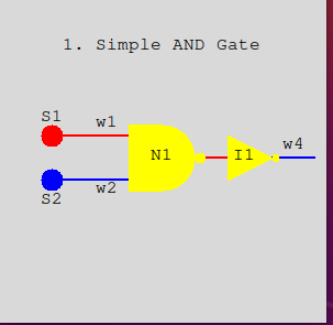
In image 1 we have switches (S1 and S2) along with NAND gate N1, and inverter I1, connected together with four wires. It is organized so that signals flow from left to right. The wires can be at either zero volts (false or 0) or plus five volts (true or 1). Their color indicates which it is. Blue indicates 0 and red indicates 1.
The switches are toggled to change their state. Click the mouse on a switch thats red and it changes to blue and also sets its output wire to blue (0). Click it again and it returns to red (1).
Switch S1 outputs to wire w1 and S2 to wire w2. In turn these wires feed the inputs of the NAND gate N1. The output of N1 is 0 if and only if both of its inputs are 1. In the image this is not the case so wire w3 (not labeled) receives 1 and passes it to the input of inverter I1. Together N1 and I1 create an AND circuit. Wire w4 simply is there to show the output of I1 and therefore the output of the circuit. w4 should be red (1) only if both S1 and S2 are red.
Run the simulation with
  $ python circ1.py
-
and click the switches to change what the wires show. You can close the image by clicking the x in the upper right corner.
Circuit 2. Making an OR Gate.
This circuit (circ2.py) is similar to circ1.py. It also has 2 levels of negation that cancel each other out. The inputs are inverted before processing by the Nand gate (N1). The output at w4 is high (red) if either or both switches S1 and S2 are high. Run circ2.py and click each high and low (and back) and see how the output on w4 changes.
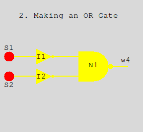
But notice that the wires in image 2 are all yellow. This is the situation at startup before any components have been activated. The yellow color is an indication that things are in limbo. Once activated the components output wires change to red or blue. Just click S1 and S2 a few times and it will all sort out.
Circuit 3. An XOR Gate
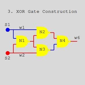
This is an exclusive-or gate constructed with 4 Nand gates. We’re seeing it here where everything has been activated (no yellow wires). The output w6 is high when S1 or S2, but not both are high. Or another way to view it is that S1 and S2 are different. The circuit is nicely symmetrical and each path from switch to output has two negations making a positive gate. Notice that output from the switches each feed an N1 input and either a N2 or N3 input. The N1 output in turn feeds both N2 and N3. Run it and play with the switches and watch the internal wires change.
Circuit 4. A simple latch
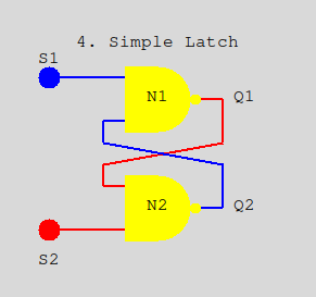
This circuit was introduced in the preceding project. The normal setting for both S1 and S2 is high. If S1 is clicked Q1 will go high (red) as shown. If S1 is clicked again Q1 will stay high being held there by the fact that Q2 has been set low. Likewise activation of S2 will have the same effect on Q2. The latch remembers the last switch that was low.
This positive feedback is the basis for computer memory. Even before electronic mechanical relays could be activated by an external input and then use one of their switches to hold on to itself in the activated state after the external activation ceased.
Play with this, activating (clicking) S1 or S2 and then clicking again. Remember the quiesent state is with both S1 and S2 high (red).
Circuit 5. An Oscillator
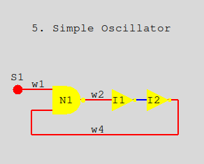
Positive feedback can hold a signal but negative feedback can introduce instability. In the figure notice that the short wire feeding I2 is low (blue). So the output of I2 is high (red). But the next thing to happen is for the output of N1 to go low as well as w2 and the input to I1. Then I1’s output goes high. A never ending circle. At least as long as with S1 is high. Clicking it off turns off the oscillation.
Play with this using different wait times between activations. The default is .01 seconds but you might find 1/10 second better with a bit of slow motion.
$ python circ5.py delay=.1
-
Code overview - Configuration files
Each of the circuits above are built as python programs that descibe the circuit as a set of linked objects (components, switches and wires). When complete the circuit is passed to the simulator program also written in python.
You can access the code for the simulator here . A import zg.py simplfies access to the Zelle graphics for the simulator.
Looking at the simplest circuit (circ1.py) pretty much shows how things work for the other 4 circuits as well. code for circ1.py
All of the objects in the animation are built from classes defined in simulator.py and consist of text blocks, switches, nand gates, inverters, and wires. The common attributes for each are position in window, a scaling for size, and a name.
The center position of each object in given in pixels. The origin of the window (0,0) is at the upper-left corner. This project uses a 300x300 pixel window.
Here once again is the starting configuration for circ1.
At the top of circ1.py the 8 text blocks are defined with a center position and a string for the text. A single font (courier) is used in a single point size.
#  circ1.py
#
from simulator import Text, Swt, Nand, Inv, Wire, gameLoop
#           center         Text to display
tt1 = Text ((150, 50), "1. Simple AND Gate")
ts1 = Text (( 50,115), "S1")
ts2 = Text (( 50,190), "S2")
tn1 = Text ((150,150), "N1")
...
The two switches s1 and s2 each carry their name, a center position, a scale factor (more later), and an initial setting at startup.
#           name    center  scale
s1 = Swt   ('s1', ( 50,130), 10, init=1)           # feeds w1
s2 = Swt   ('s2', ( 50,170), 10, init=0)           # feeds w2
The Nand and Inv gates are similar but they are not given initial output values.
n1 = Nand  ('n1', (150,150), 30)                   # feeds w3
i1 = Inv   ('i1', (230,150), 20)                   # feeds w4
-
Wires connect a single output from a switch or gate to zero or more inputs of other gates. Wires form a path defined by a tuple of (x,y) points starting from an output and ending at an input of one or more gates.
If a wire is left open (like w4) it’s only used to show the output of its gate by its color.
#         name   wire points         fed-by  dest(s)
w1 = Wire('w1', (( 50,130), (120,130)), s1, [(n1,0)]) # s1 to n1 pin 0
w2 = Wire('w2', (( 50,170), (120,170)), s2, [(n1,1)]) # s2 to n1 pin 1
w3 = Wire('w3', ((190,150), (210,150)), n1, [(i1,0)]) # n1 to i1
w4 = Wire('w4', ((240,150), (290,150)), i1, [])       # displays i1 output
-
The destination(s) of a wire is a list of tuples. Each tuple contains a gate object and the input (0-n) connected. A wire can also be connected to multiple inputs as you will see in circ3.py. The If a None value precedes an (x,y) tuple in the path it signals that the path should be broken and a new branch started at (x,y) which will lead to another input.
Finally we get to the main function. The function gameLoop in the simulator is called and passed a list of everything to draw in a list. Wires are first, then gates and finally text labels. Function gameLoop can also be passed items, usually switches, that are to be activated at startup.
def main() :
                         # in drawing order
    gates = (w1,w2,w3,w4,n1,i1,s1,s2,tt1,ts1,ts2,tn1,ti1,tw1,tw2,tw4)
    gameLoop(gates,[s1,s2])
-
Code overview - The Simulator
The file simulator.py contains the class definitions that are used by the circuits in composing their components. The classes are Text, Wire, Inv, Nand and Swt.
When a gate or switch is activated then it recomputes its output from its inputs or current state. If the output changes then the wire connected to the output is passed the new value (0 or 1). In turn the wire changes its color appropriately and sends the value to the inputs of other gates it is connected to. These other gates are then queued for activation in the next cycle (coming up). That’s pretty much it. Here is the central piece in the Wire class.
    def takeValue(self, value) :
        if value != self.output :
            self.output = value
            self.recolor()
            for gate,con in self.connects :
                gate.takeInput(con,value)
                queueItem(gate)

    def recolor(self) :
        if self.output == None : color = "yellow"
        else :                   color = ["blue","red"][self.output]
        for line in self.lines : zg.recolor(line, color)
-
The Game Loop
The pending queue holds objects waiting to be activated. The FIFO queue is used to crudely keep possible mutliple paths of computation in sync with each other.
As mentioned, gameLoop is called from the circuit with a list of gates and an optional list of gates to activate immediately. This starts off the pending queue. All components of the circuit are drawn in the window and the loop is run each delay seconds. The default is 1/100
On the command line we can override the delay value. A bigger number (like 1) gives you a slow motion effect. Also setting debug=1 on the command line will print lines to the console showing objects being queued for activation and their actual activations which you can watch in parallel with the graphic.
pending = []
def queueItem(item) :
    if item not in pending : pending.append(item)

def gameLoop(gates,trigger=[]) :
    global pending
    pending += trigger
    for item in gates : item.draw()
    clock = 0
    delay = sarg.Float("delay", .01)
    debug = sarg.Int("debug", 0)
    while True:
        if debug and pending :
            print("Pending", [x.name for x in pending])
        for i in range(len(pending)) :
            gate = pending.pop(0)
            if debug : print("gameLoop activating", gate.name)
            gate.activate()
        time.sleep(delay)
        clock += 1
-
At the bottom of the game loop we check if the mouse has been clicked. If so, then objects having a takeClick method are called to see if the click happened within them and if so respond accordingly. Only the switches have this method at present.
       try    : pos = win.checkMouse()
        except : break   # exit clean if window closed
        if pos :
            for gate in gates :
                if 'takeClick' in dir(gate) :
                    gate.takeClick(pos)
-
You can download this zip file for this project
If you have comments or suggestions You can email me at mail me
Copyright © 2021 Chris Meyers and Fred Obermann
* * *